Overview
The neutron user facilities at ORNL use and develop a wide range of high pressure cells and devices that are available to the user program through the High Pressure Group, the High Pressure Diffractometer SNAP, through collaborative efforts with the Institute of Solid State Physics at the University of Tokyo, as part of the US-Japan Cooperative Program on Neutron Scattering, as well as through individual beamline efforts.
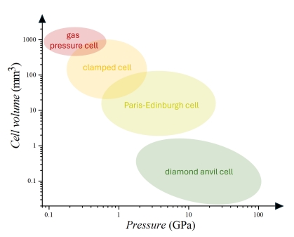
Typical cell volumes and pressure ranges afforded by the various pressure cells in use with ORNL’s neutron scattering program.
Cell types, corresponding sample geometries and sizes, pressure media and pressure application are typically optimized for given instrument geometries and science questions. They can be loosely grouped into these seven different general types. Please refer to the individual tabs for details:
Cylindrical gas pressure cells and gas intensifiers
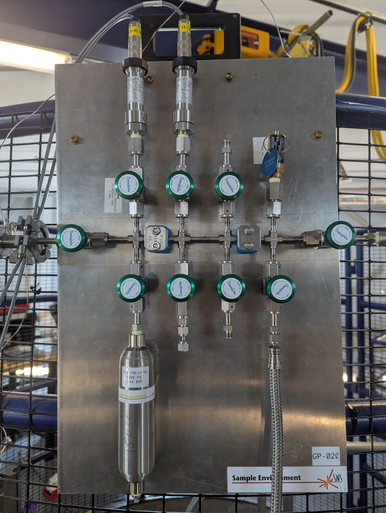
Various cylindrical gas pressure cells operated in conjunction with the appropriate gas intensifiers are available. They are typically used across a number of diffractometers and spectrometers at the SNS and HFIR. CO2, CH4, He, N2 and Ar are some of the gases commonly used in these cells. Other gases may be utilized, pending technical review. An example of use and development for diffraction at SNS can be found here: Santos et al. RSI 89, 092907 (2018).
For specific experiments, please contact the instrument team of the instrument in question. For general inquiries and possible future opportunities please contact Antonio dos Santos.
Gas cells
| Cell type | Max pressure | Sample bore diameter | Max sample height | Available gases/Notes |
|---|---|---|---|---|
| TiZr Gas Pressure Cell | 1.2 kbar (17,600 psi) | 6.35 mm (.25″) | 63.5 mm (2.5″) | TiZr body |
| 100 bar cell | 100 bar (1500 psi) | 6 mm (.25″) | 57 mm (2.25″) | Aluminum body |
| Small Harwood Gas Pressure Cell | 6 kbar (88,000 psi) | 38 mm (1.5″) | 50.8 mm (2″) | Aluminum body |
| Hydrogen Gas Pressure Cell | 7 kbar (102,00 psi) | 7 mm (.27″) | 70 mm (2.75″) | CuBe body, H2 compatible |
| Small Auto-Frettage Gas Pressure Cell | 4.8 kbar (70,400 psi) | 6 mm (.236″) | 60 mm (2.37″) | Aluminum body |
| Large Auto-Frettage Gas Pressure Cell | 4.8 kbar (70,400 psi) | 30.5 mm (1.2″) | 60 mm (2.37″) | Aluminum body |
Gas intensifiers
| Model | Max pressure | Automation | Available gases |
|---|---|---|---|
| Teledyne ISCO pump 100HLf | 10,000 psi.7 kbar | Pressure/Flowrate control | H2 compatible |
| Teledyne ISCO 65HP | 24,000 psi1.65 kbar | Pressure/Flowrate control | Oil only |
| Teledyne ISCO 65D | 20,000 psi1.38 kbar | Pressure/Flowrate control | Non-H2 compatible |
| SITEC 7 KBar Gas Intensifier | 100,000 psi7 kbar | NA | H2 compatible |
| 4 KBar Piston Liquid Pressure Generator | 60,000 psi4 kbar | NA | Liquid only |
| SITEC 10 KBar Pressure Generator | 145,000 psi10 kbar | Pressure control | He only |
The neutron user facilities at ORNL use and develop a wide range of high pressure cells and devices that are available to the user program through the High Pressure Group, the High Pressure Diffractometer SNAP, through collaborative efforts with the Institute of Solid State Physics at the University of Tokyo, as part of the US-Japan Cooperative Program on Neutron Scattering, as well as through individual beamline efforts.
Significant capabilities are also available and supported through the beamline teams themselves. Examples include the AGES system, as used on POWGEN, or the high temperature gas flow environment developed for NOMAD.
Please contact the instrument teams directly for further details on possible experiments.
Pressure cells and devices for small angle neutron scattering
The SANS beamlines use specialized pressure cells that are optimized for the specific SANS geometry and science questions.
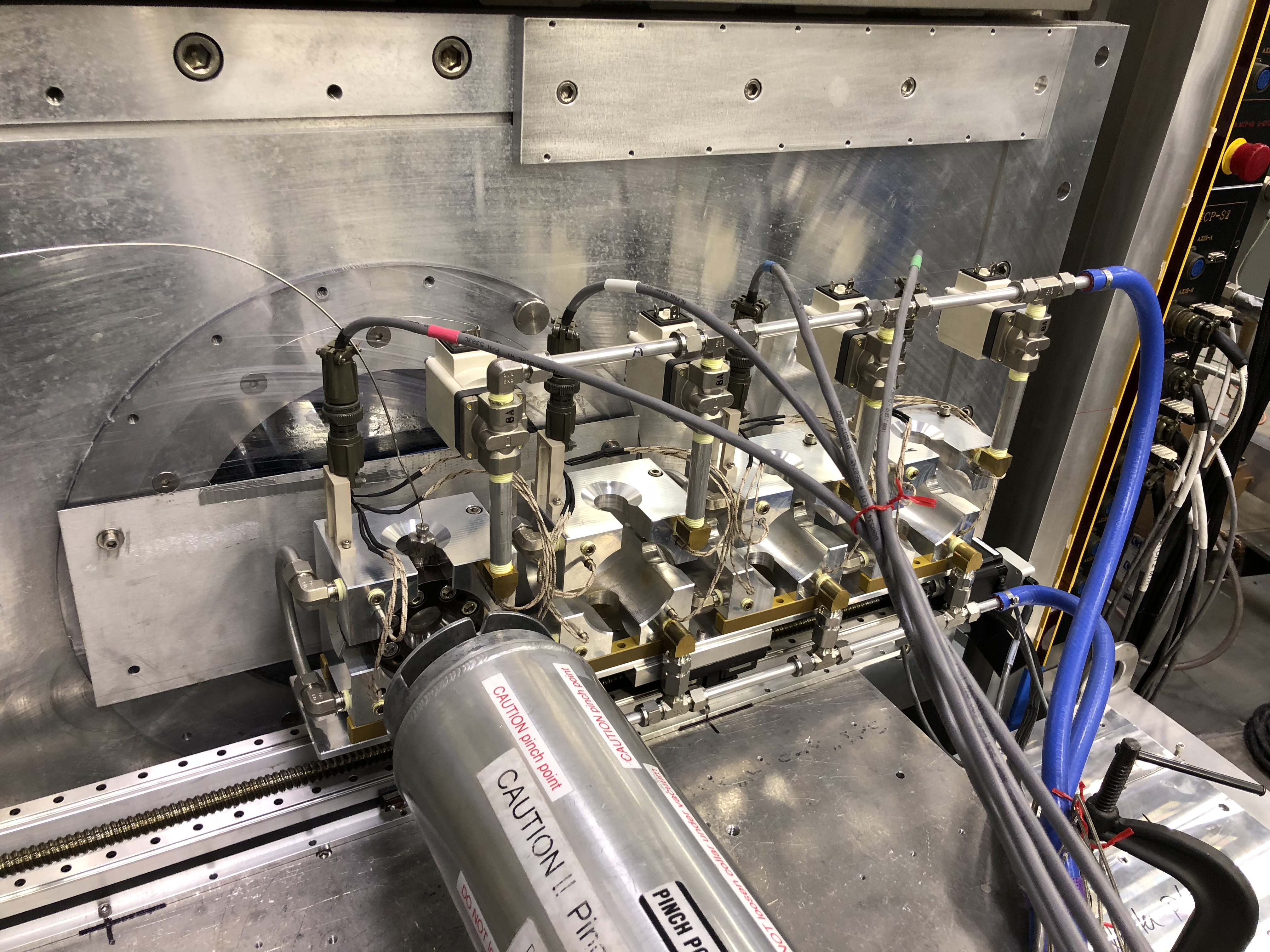
Dome cells: The dome style pressure cells can achieve 1kbar of pressure with CO2, CH4, He, N2 and Ar gases. The dome cells have heating rod temperature control up to 200°C with a manifold for mixing gases.
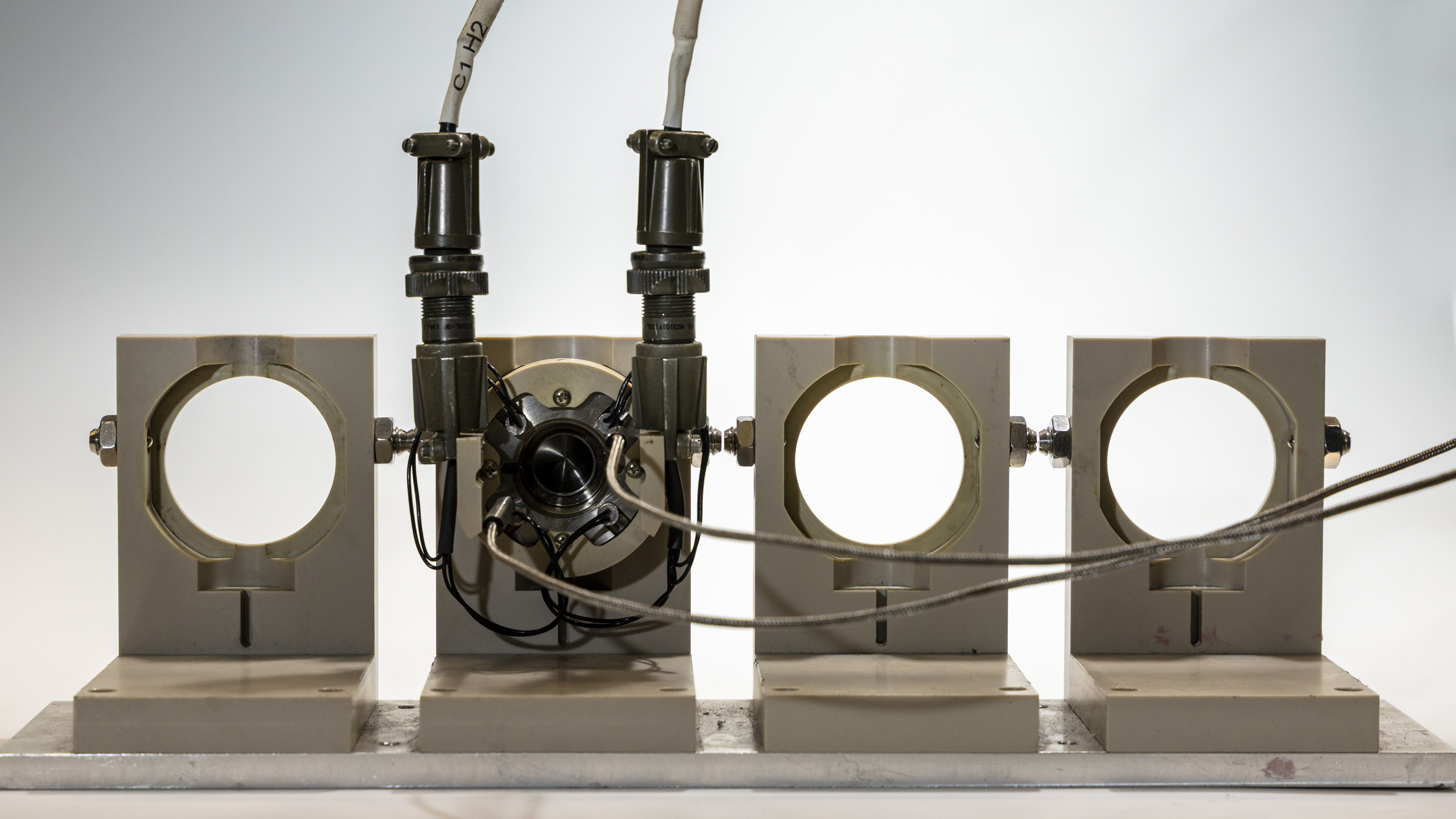
Extended McHugh pressure cells: The McHugh pressure cell can achieve a pressure of 2 kbar for CO2, CH4, He, N2 and Ar, with water bath temperature control from 10-80°C. The cell body end section is optimized to achieve a pressure cell with an extended angle pressure.
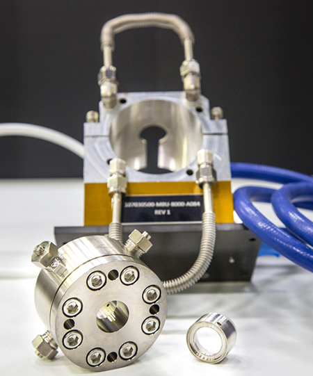
Please contact the SANS beamlines for further details on possible experiments and future opportunities.
Clamped piston-cylinder cells
A piston-cylinder clamped cell consisting of a pre-stressed CuBe insert (not visible), an Al sleeve, two Al clamping bolts, several tungsten carbide pistons, and a steel piston with a diamond window for optical access (bottom center).
A range of piston-cylinder cells for neutron scattering applications are available for use across various SNS and HFIR diffractometers and spectrometers. These cells are typically pressurized offline outside the beamline and pressure is clamped in for measurement. They are compatible with other extreme environments such as (ultra-)low temperature and high magnetic fields in some cases. Various designs of cells as well as complimentary tools continue to be developed.

An example of an in-house development is a clamped cell with optical access through a diamond window that allows for in situ pressure measurement via ruby or strontium borate fluorescence: Podlesnyak et al. HPR 38, 482 (2018).
The specifics of each experiment are typically planned carefully around the sample, its scattering profile, powder vs. single crystal, the required pressure transmitting medium, as well as around the desired beamline and the given science question. Possible cells and sample geometries will thus vary.
For experiments on a specific instrument, please contact the instrument team directly. For general enquiries, further possible experiments, and future opportunities please contact Yan Wu or Jamie Molaison for SNS.
Clamped cells
| Cell type | Max. Pressure (GPa)* | Material in beam | Sample Dimensions (mm) | Comment |
|---|---|---|---|---|
| Small Uwatoko-style CuBe cell | 1.8 GPa | CuBe (6.3 mm) | Ø2.5 x 8 | compatible with ULT and high magnetic field |
| Large bore Uwatoko-style CuBe cell | 1.5 GPa | CuBe (12 mm) | Ø6 x 21 | compatible with ULT and high magnetic field |
| Al-sleeved, CuBe insert cell | 2 GPa | CuBe (10 mm) + Al7075 (17.3 mm) | Ø4.8 x 18 | compatible with ULT and high magnetic field |
| Al-sleeved, CuBe insert cell with diamond window | 2 GPa | CuBe (10 mm) + Al7075 (17.3 mm) | Ø4.8 x 18 | compatible with ULT and high magnetic field |
| Al-sleeved, NiCrAl insert cell | 2 GPa | NiCrAl (10 mm) + Al7075 (17.3 mm) | Ø4.8 x 18 | compatible with ULT and high magnetic field |
| NiCrAl cell | 2 GPa | NiCrAl (10 mm) | Ø4.8 x 10 | compatible with ULT and high magnetic field |
| TiZr cell | 1.1 GPa | Ti-47.8wt%Zr (10 mm) | Ø4.8 x 10 | compatible with ULT and high magnetic field |
*NOTE: Nominal pressure is given here as benchmark value only. Experimental pressures are often lower due to a number of factors.
Uniaxial pressure cells and devices
A uniaxial pressure stick is available in the user program on multiple beamlines at HFIR including WAND2 and four triple-axis spectrometers VERITAS, CTAX, TAX and PTAX. The stick is compatible with liquid helium cryostat (1.8K-300K) and 6 Tesla Vertical Field Magnet (1.8K-300K, 0-6T) facilitating in situ control of uniaxial pressure for single crystal neutron scattering studies. Up to 300 lbs calibrated force can be applied and transmitted to the sample by a rigid rod. The stick is the 3rd generation instrument designed and built for ORNL in collaboration with the Rice University (link to the manual). An example publication from this instrument can be found here: Tam et al., PRB 95, 060505(R) (2017).
Note that sample preparation is the most critical step for a uniaxial pressure experiment. To apply uniaxial pressure along one specific crystallographic direction, the single crystal sample needs to be cut precisely with two parallel flat facets relative to its orientation and geometry. As illustrated in Figure. 1(c), the maximum sample dimension the cell can accommodate is ~4mm x 8.5mm (pressed area, flat facet area) x 10 mm (sample thickness along the applied uniaxial pressure direction). Because the maximum force can be applied on the sample is 300 lbs, smaller pressed area is preferred if you want to apply higher uniaxial pressure, (e.g., the maximum pressure can be up to ~2 GPa if the pressured area is 1mm2).
Please contact the beamline scientists for further details on possible experiments.
Paris-Edinburgh cells
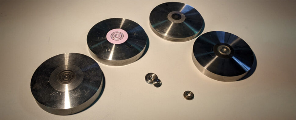
The ORNL Paris-Edinburgh cell program commenced at the SNS’s High Pressure Diffractometer, SNAP, where still the majority of experiments with this type of cell are conducted. See here for capabilities on the SNAP beamline.
Over the last few years, the use of the cells has been extended to other beamlines and is now available in the user program of HFIR’s WAND2: Donnelly et al. HPR 42, 213 (2022).
Additionally, use at various SNS spectrometers has been explored. More details on this to follow as capabilities become available in the user groups.
For experiments on SNAP , please directly contact the SNAP Beamline Team. For further possible experiments, future opportunities and general enquiries, please contact Jamie Molaison.
| Cell type | Max load |
|---|---|
| VX1, steel | 40 tons |
| VX3, steel | 200 tons |
| VX5, steel | 150 tons |
| Geometry | Material | Max pressure* |
|---|---|---|
| Single-toroidal | Cubic boron nitride | 7-9 GPa |
| Single-toroidal | Tungsten carbide | 6-7 GPa |
| Single-toroidal | Zirconia toughened alumina | 7-9 GPa |
| Double-toroidal | Polycrystalline diamond | 16-20 GPa |
*NOTE: Maximum possible pressure varies depending on compressibility of sample, pressure medium, exact loading and details of a given experiment.
Neutron diamond anvil cells
The ORNL neutron diamond anvil cell program commenced at the SNS’s High Pressure Diffractometer, SNAP, where still the majority of experiments with this type of cell are conducted. A comprehensive development program on diamond cells with single-crystal diamonds is in progress and the latest development has now achieved over 100 GPa at room temperature: B. Haberl et al. Sci. Rep. 13, 4741 (2023).
Combination with low temperatures down to 7-10 K limits the pressure to 20-40 GPa. See here for capabilities on the beamline.
ORNL also supports a DAC gas loader that is most typically used for loading of Ar as pressure-transmitting medium into SNAP DACs. Please contact the beamline team for further details, capabilities and constraints.
In addition to these single-crystal anvil DACs specific to the SNAP High-Pressure Diffractometer, the use of large culet anvils for spectroscopy and single-crystal samples has been explored. The most common cell resulting from these efforts uses polycrystalline Versimax® anvils and is capable of pressures up to a maximum of 10 GPa. This cell has been trialed for spectroscopy and has been used across various single-crystal diffractometers at SNS and HFIR. See here for more details: Haberl et al. HPR 37, 495 (2017) and Haberl et al. RSI 89, 092902 (2018).
For experiments on SNAP, please directly contact the SNAP Beamline Team. For experiments on DEMAND, please directly contact Yan Wu. For further possible experiments, future opportunities and general enquiries, please contact Jamie Molaison.
Neutron diamond anvil cells
| Cell type | Anvils | Temperature | Sample type** | Typical culet | Max pressure*** |
|---|---|---|---|---|---|
| Megabar DAC, steel | Single crystal | RT only | powder | 1 mm – 700 μm | 50-100 GPa |
| Megabar DAC, steel | Single crystal | RT – 7 K | powder | 1.5 mm | 20-40 GPa |
| Clamped DAC, CuBe | Versimax | RT – 5 K* | single crystal | 3 mm | 8-10 GPa |
*NOTE: Development is in progress to couple these DACs with ultra-low temperatures below 1.4 K.
**NOTE: Development on the use single-crystal samples with single-crystal anvil DAC is in progress.
***NOTE: Maximum possible pressure varies depending on compressibility of sample, pressure medium, exact loading and details of a given experiment. The provided values are to simply provide a benchmark.
Policy for the provision of neutron diamond anvil cells:
The equipment has to be operated under the health and safety rules provided and the advice of the instrument staff must be followed.
The need of a DAC has to be explicitly requested in the beamtime proposal, otherwise the provision of a DAC cannot be guaranteed.
Users must contact the instrument team as soon as possible (minimum 8 weeks) prior to the beamtime to discuss details of the experiment.
Users should arrive well in advance for the experiment (typically 2-3 days) and always a full day before beamtime starts.
Standard ORNL DACs are provided.
One DAC will be provided per beamtime visit. Its use is solely for the completion of the proposed experiment. Provided that adequate resources and components are available, a second DAC might be available, contingent upon instrument staff approval.
Samples need to be available at least a week prior to the beamtime to allow for the preparation of the DAC as soon as resources are available.
In special cases, samples may be requested at the beginning of the cycle for feasibility assessment. Beamtime scheduling may be contingent on those results.
A successful loading is not guaranteed, especially on the first attempt.
– Unsuccessful preparations may lead to cancellation of the beamtime, and the user should resubmit the (modified) proposal.
– Alternatively, the beamtime can go ahead if there is an approved alternate sample added to the proposal.
Various pressure-transmitting media are available; gas loading has to be requested preferably in the beamtime proposal. It should always be discussed in advance.
Staff members that make significant contributions for the preparation of the cell and sample loading should be co-authors of any publication resulting from the experiment.
Any decision regarding any issue that affects the safety of the equipment ultimately lies with the instrument staff.
Mechanical Loading
The use of a load frame is supported through the instrument team at the VULCAN beamline.
Specifically, dedicated in situ mechanical loading is possible using the VULCAN MTS Loadframe: +/-100KN tension/compression, and 400Nm torsion, +/-100mm stroke, 270o rotation. Centroid control. 30Hz rated cyclic loading, and uniaxial movement as low as 10-6 mm/s. Induction heating in the air with loading. Temperatures are limited by materials oxidation resistance and induction coupling.
First experiments using this load frame are described in K. An et al., Metallurgical and Materials Transactions A, 42, 95 (2011). For further publications please refer to VULCAN’s publication list.
Please contact the VULCAN instrument team for details on capabilities, experiment planning and future opportunities.