Multimodal Advanced Radiography Station
Mission Statement
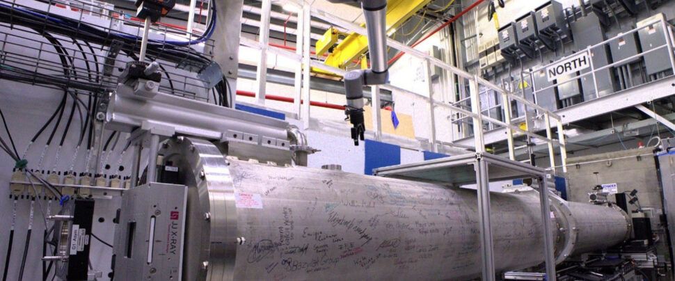
The Multimodal Advanced Radiography Station (MARS), HFIR beamline CG-1D, provides high-resolution radiography and computed tomography imaging capabilities across multiple length and time scales for diverse applications.
Instrument Description
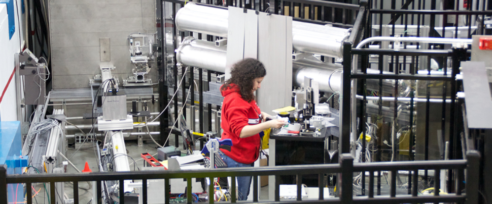
MARS is designed as a flexible platform on which to perform high-spatial and high-temporal resolution imaging using an intense, polychromatic cold neutron beam. In addition, white-beam neutron grating interferometry (nGI) is now offered to provide spatially-resolved neutron phase- and small-angle scattering contrasts (see Ref. 4). The instrument configuration, including beam collimation, sample platforms, sample environments, and detectors may be tailored for each measurement. The unique imaging capabilities at MARS complement those of the VENUS instrument at the Spallation Neutron Source, which is dedicated to neutron imaging with an emphasis on time-of-flight (i.e., energy-dependent) contrast.
Instrument papers
- Torres et al., “Overview of MARS: the Multimodal Advanced Radiography Station at the High-Flux Isotope Reactor,” In: Craft, A.E., Bilheux, H.Z. (eds) Proceedings of the 12th World Conference on Neutron Radiography. WCNR 2024. Springer Proceedings in Physics, vol 348. Springer, Cham. DOI: 10.1007/978-3-032-15003-5_33
- Santodonato et al., “The CG-1D Neutron Imaging Beamline at the Oak Ridge National Laboratory High Flux Isotope Reactor,” Physics Procedia 69, pp. 104-108 (2015). DOI: 10.1016/j.phpro.2015.07.015
- Crow et al., “The CG1 instrument development test station at the high flux isotope reactor,” Nuclear Instruments and Methods in Physics Research Section A: Accelerators, Spectrometers, Detectors and Associate Equipment 634, no. 1, pp S71-S74 (2011). DOI: 10.1016/j.nima.2010.06.213
- Zhang et al., “Neutron Grating Interferometry at the High Flux Isotope Reactor,” In: Craft, A.E., Bilheux, H.Z. (eds) Proceedings of the 12th World Conference on Neutron Radiography. WCNR 2024. Springer Proceedings in Physics, vol 348. Springer, Cham. DOI: 10.1007/978-3-032-15003-5_41
Applications
MARS supports a broad range of materials research across natural and physical sciences, engineering, and advanced manufacturing. Research areas that can benefit from MARS include, but are not limited to…
- Additive Manufacturing – Porosity; internal structure; quantitative comparative analysis of neutron-computed tomography data with engineering drawings
- Energy Storage and Generation – Operando ion transport in energy storage materials; three-dimensional mapping of ions in electrodes; fluid transport in fuel cells and electrolyzers
- Nuclear Materials – In situ molten salt diffusion, solubility, and gas transport at high temperatures; inhomogeneities in nuclear fuel material
- Transportation Technologies – Particulate deposition in vehicle parts; two-phase transport in heat pipes; multiphase constrained jet flows; metal casting; reservoir flow, creation, and production
- Plant Systems Biology – Partitioning, transport, and fate of carbon fixed by plants; carbon biosequestration; modified bioenergy feedstock plants; cavitation and gas embolism in plants
- Plant-Soil-Groundwater Systems – Transport and interactions of fluids in porous media; water infiltration and aquifer recharge; plant-plant and plant-fungal interactions; change in pore structure and voids after repeated thawing and freezing of permafrost soil
- Biological, Forensic, and Medical Studies – Internal structures; mapping contrast agents; cancer research; wood and biomass pyrolysis
- Food Science – Water migration and degradation through time
- Archeology and Paleontology- Examination of cultural artifacts; 3D phase and structural analysis of fossils
Specifications
| Wavelength | Polychromatic (white beam): 0.8 < λ < 6 Å, peak at 2.6 Å, and average of 3.6 Å |
| Sample positions, L (L: distance from aperture) | Downstream position: L = 6.59 m Upstream position: L ~ 1.0 m |
| Collimation, L/D (D: pinhole size) | Pinhole apertures Downstream: 400 – 2000 Upstream: 60 – 300 Slit apertures (3 mm x 20 mm) both horizontal and vertical are now available |
| Beam size | Downstream: 8.6 cm x 8.6 cm with slits Upstream: ~3 cm diameter |
| Detectors | Charge-coupled device (CCD) and scientific complementary metal-oxide-semiconductor (sCMOS) cameras optically coupled to Zn:S or Gadox-type scintillators of various sizes and thicknesses. |
More information
- ORNL neutron imaging website, including Jupyter notebook tutorials
- ORNL neutron imaging GitHub repository
MARS Instrument Team
Please select link below to email the instrument team. Be sure to include your name and email address.

MARS User Guide
Experiment planning
The following steps should be taken to plan a neutron imaging experiment at MARS and/or VENUS.
- Discuss proposed measurements with instrument scientists at MARS and/or VENUS.
- Choose an imaging modality. Table 1 summarizes the available modalities, common applications, and at which instrument to conduct those measurements.
TechniquePrincipleExample ApplicationsInstrument selectionAttenuation-Based RadiographyAttenuation contrastHydrogen mapping, fuel cell operation, cultural heritage, materials screeningMARS: highest sensitivity and spatial resolution
VENUS: highest penetration and wavelength discrimination Computed Tomography (CT)3D reconstruction from projectionsCorrosion/hydrogen mapping, battery electrode degradation, porous materialsMARS: fastest CT or highest spatial resolution
VENUS: hyperspectral CT, higher penetrationBragg-Edge Imaging (BEI)Crystallographic edge absorptionResidual stress mapping, phase distribution in metalsVENUS onlyPhase-Contrast ImagingRefractive index differencesSoft tissues, low-Z materials, porous foamsMARS: qualitative only (under development at VENUS)Polarized Neutron ImagingSpin-dependent scatteringMagnetic domain imaging, superconductorsMARS only (under development at VENUS)Dark-Field ImagingSmall-angle scattering effectsFiber composites, microcrack detection, foams, heterogeneous particle/void distributionsMARS: qualitative only (under development at VENUS)Resonance ImagingNuclear capture in epithermal rangeNuclear materialsVENUS: 2D only (3D under development)In Situ/Operando Imaging (time-resolved imaging)Controlled environment operationBattery cycling, phase transitions/solubility, fuel cell operation, fluid dynamicsMARS: fastest
VENUS: wavelength discrimination, cycling motion, event mode measurementsTable 1. Image modalities - Estimate the total neutron transmission through the sample and its container,
- Use the online transmission calculator: https://neuit.ornl.gov/transmission
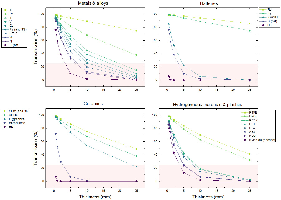
- Aim for minimum 20-25% total transmission for CT and 15-20% contrast for best results
- Figure 1 shows the total transmission through common materials encountered at MARS
Determine the minimum spatial and temporal resolutions required to answer the research question(s).
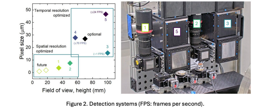
- Standard setup: ~16 μm pixel size (~45 μm effective resolution under ideal conditions), 8.6 cm x 8.6 cm field of view, 30-to-60s exposure
- Figure 2 summarizes the currently available detector systems
- For computed tomography (CT), estimate the total measurement time based on the selected detection system.
- Table 2 summarizes the detection systems with exposure times
- Total CT time T is a function of sample (effective) diameter D, pixel size d, and exposure time t: T=(π/2 D/d)t where the quantity in parentheses is the number of projections collected at incremental angles.
- Two common sample sizes: (ex. 1) 6 mm diameter and (ex. 2) 25.4 mm diameter
- Make note of all materials and equipment that will be within 30cm of the beam and enter them as samples in IPTS. For example, battery cell holders, sample containers/frames, shielding, tubing/lines, power and communication cables. NOTE: once taken into HFIR, all materials (samples, holders, equipment, etc.) require release by radiological control technician (RCT), and anything within 30cm of the beam requires activation calculations along with RCT survey.
- Custom equipment must be discussed with instrument staff well in advance of beam time, and equipment must be inspected and approved by appropriate ORNL safety personnel before use. Be prepared to write a job hazard analysis (JHA) with instrument staff, which includes steps of equipment operation, their associated hazards, and actions to mitigate those hazards.
- Sample & equipment shipping: refer to the online shipping guide for when, how, and where to ship as well as disposition information.
- X-ray imaging/CT (https://neutronimaging.ornl.gov/capabilities/) may be available provided that
- Measurements are feasible, safe, and equipment is operational
- Instrument staff have time and resources to perform measurements
- Samples are shipped well in advance of neutron beam time, coordinated with instrument staff
Running the experiment
Users will be trained to safely operate MARS equipment and will be provided with a list of contacts for any issues. Here are some useful links to control or monitor an experiment remotely.
- Remote beamline controls through https://analysis.sns.gov/:
- Launch Session
- Login using XCAMS credentials
- Go to Applications (top left), Remote Experiments, and then CG-1D MARS
- Login again using XCAMS
- Open a terminal and type css to launch beamline controls (may need to select a layout from the dropdown menu at the top-left)
- Access to the sample environment computer (e.g., to control the Potentiostat) is done within this second instance and going to Applications > Sample Environment. Username and password will be provided by instrument staff.
- Instrument webcam (must be on ORNL visitor network), username and password will be given by instrument staff.
- Online catalogue (OnCaT) with all collected data (public website, requires XCAMS login), wait ~5 minutes for data transfer.
- Beamline monitoring to track process variable (PV) values (public website, requires XCAMS login).
- Communicate with instrument staff primarily using Slack. Please go to https://ornlneutronsciences.slack.com/ in your web browser and login using your XCAMS credentials to be added to the workspace. Provided you are on the proposal with the same email you will be automatically added to the channel once you have joined the workspace.
After the experiment
All materials and equipment that were within 30cm of the neutron beam are considered radioactive materials and will require detailed neutron activation calculations, including complete composition, mass, and exposure time, as well as release by a radiological control technician (RCT). Some materials such as steel will remain activated for months to years.
Shortly after the experiment, all data will be normalized, and CT data will be reconstructed. Instrument staff will update the Slack channel with final data location(s).
- Additional data processing such as image/pixel binning, registration, and other manipulations can be performed by users using the available Jupyter notebooks on the analysis cluster: https://analysis.sns.gov/ and going to Applications > Analysis-imaging > Jupyter Notebooks. Tutorials are available online at https://neutronimaging.ornl.gov/tutorials/imaging-notebooks/
- Additional or customized notebooks may be available upon reasonable request from the Computer Instrument Scientist (CIS): https://neutrons.ornl.gov/mars/team
- Amira/Avizo visualization and segmentation software may be available for limited use, based on availability of licenses.
Note that X-ray imaging/CT after neutron irradiation at MARS is challenging and may not be possible. Discuss these needs with instrument staff.
Publications and reporting requirements
Intent to Publish: As a condition for performing nonproprietary research, the US Department of Energy requires users to publish results from their research. Authorship of publications based on research from these facilities should reflect the normal considerations of recognizing collaborations. It is also important to take into account the considerable efforts of instrument scientists in their role of designing, constructing, and/or operating the instrument and related facilities. Results are typically published in peer-reviewed journals, proceedings, or presentations at technical conferences. Proprietary users are not required to publish.
Credit Line: All publications based on work done in whole, or in part, at the Spallation Neutron Source or the High Flux Isotope Reactor at Oak Ridge National Laboratory should acknowledge the facility (or facilities) with this required statement:
This research [or, A portion of this research] used resources at the High Flux Isotope Reactor [and/or Spallation Neutron Source, as appropriate], a DOE Office of Science User Facility operated by the Oak Ridge National Laboratory. [If applicable: The beam time was allocated to [Instrument] on proposal number IPTS-XXXXX.X.]
In addition, users are asked to credit the instrument(s) used in the body of the paper.
Contribute to Our Publication Records: After your results have been published, submit the paper’s citation information via the Publications Portal.
MARS Videos
ORNL researchers were able to use neutron imaging (computed tomography or CT) to see inside of Inconel 718 turbine blades that were made using additive manufacturing, or 3D printing, to non-destructively study the internal structure of these blades, to model internal flow based on the imaged turbine and therefore improve the design of the blades. Anyone can look at the outside of a turbine blade, but imaging the internal structure without cutting the piece apart is very challenging. The interior surface roughness, as measured with neutrons, can be modeled to study/estimate the changes in air flow.
Nondestructive examination of complex additive manufactured components using neutrons is a valuable technique for imaging and measuring residual stress. Read more here.