High Intensity Diffractometer for Residual Stress Analysis

Mission Statement
Scientists and engineers use the HB-2B High Intensity Diffractometer for Residual stress Analysis (HIDRA) to study residual stresses in steel, aluminum, superalloys like Inconel, and other such structural materials. Elastic strain in these materials can be determined by measuring their interplanar atomic spacing, and this instrument is designed to use the high- penetration power of neutrons to generate “maps” of the strain resulting from residual or applied stresses in bulk materials. A detailed understanding of residual stresses is critical for the safe and effective functioning of virtually every type of structural engineering material.
Instrument Description
The HB-2B HIDRA beam line is optimized for strain measurement and determination of residual stress in engineering materials. The incident beam is delivered at a fixed angle of 88° by a double-focusing Popovici-Stoica silicon monochromator (replacement unit installed Fall 2025, HFIR Cycle 513). Both vertical and horizontal focusing are used. The wavelength is chosen from a variety of monochromator crystal settings with a selection of wavelengths from 1.45 to 2.67 Å.
The sample goniometer is designed for spatial scanning of residual stresses at depths from a millimeter to several centimeters in most metals—for example, ~3–4 cm in steel and greater than 10 cm in aluminum. Spatial resolution at a fraction of a millimeter is possible depending on the material. The scattering from the test sample is recorded with a 30 cm × 30 cm 2D position-sensitive detector (DENEX 300TN) located approximately 1 meter from the sample. The nominal scattering angle (at the center of the detector) can be set from 65° to 120° but is normally near 90°. The detector spans approximately 17° in 2θ.
In situ loading experiments are supported at HIDRA using a Psylotech load frame shared across multiple HFIR/SNS beamlines. Contact instrument staff for availability and compatible specimen geometries.
Applications
HIDRA offers an integrated suite of web-based experiment planning tools and open-source analysis software that together support every stage of a residual stress measurement campaign — from pre-proposal feasibility assessment through final stress/strain calculation.
HIDRA Planning Suite (NOVA / NDIP)
Before writing a proposal or scheduling beam time, users can assess experiment feasibility and estimate required measurement time using the HIDRA Planning Suite, hosted on ORNL’s Neutron Data Interpretation Platform (NDIP). The tools run entirely in a web browser — no software installation is required — and are accessible to all registered ORNL users via XCAMS/UCAMS credentials.
The Planning Suite includes two integrated tools:
Count Time Estimator — answers the fundamental planning question: how long must I count per measurement point for my material, gauge volume, and sample depth? The tool uses a calibrated peak-height scaling law combined with Lambert-Beer neutron attenuation to compute required exposure times. Users select from a built-in material library (ferritic steel, austenitic steel, aluminum, nickel, Inconel 718, copper) or enter a custom alloy composition and density. The recommended monochromator setting for each material is highlighted automatically. Results include interactive count-time contour maps and attenuation curves that can be exported as high-resolution figures for inclusion in proposals.
Mapping Planner — simulates a complete residual stress mapping scan on a user-defined sample geometry. For every planned measurement point the tool computes incident and diffracted beam path lengths through the material, applies the attenuation correction, and classifies each gauge volume location as Fully Buried, Partially Buried, or Outside the sample. Results are displayed in an interactive 3D visualization with beam-path overlays, and a downloadable CSV table reports per-point burial status, path lengths, and required count times. Sample geometry can be entered as a simple cuboid or uploaded as a custom STL file for complex shapes such as welds, pressure vessels, or turbine blades.
The Count Time Estimator and Mapping Planner are linked: once count-time parameters are set in the Estimator, a single click transfers them to the Mapping Planner, ensuring consistent physics across both tools.
Access the HIDRA Planning Suite through the Engineering Diffraction category on the NOVA dashboard at ndip.ornl.gov/nova.
Specifications
| Beam Spectrum | Thermal |
| Selectable Wavelength (Monochromator setting) | 88°, λ = 1.452 Å (Si 511); 1.452 Å (Si 333); 1.540 Å (Si 422); 1.731 Å (Si 331); 1.886 Å (Si 400); 2.275 Å (Si 311); 2.667 Å (Si 220) |
| Flux on sample | 3 x 10⁷ n/cm2/s (Si 331 and Si 400) |
| Detector angle range | 65–120° (via detector arm rotation); optimal near 90° |
| Detection system | 30×30 cm 2D Denex |
| 2D Detector Coverage | 17° 2θ |
| Z elevator Z translation | Z ± 250 mm 39 cm table to beam height |
| Nominal Gauge volume | Slits: Width: 0.3–5 mm; Height: 0.3–25 mm Radial Collimator: Width: 3 mm |
| Peak location precision | 0.0003° 2Θ (~100–150 microstrain) |
| Sample environments | Huber Eulerian cradle and/or phi-chi stage for tensor and texture Vacuum and environmental furnaces CrESL creep electrostatic levitator Integration with flexible specialized sample environments |
| Max. Sample Size | Weight Limit: up to 2,400 kg (configuration dependent; contact instrument staff for large or unusual samples) Dimensions: consult with team |
New in 2025: A replacement Popovici-Stoica monochromator was installed in HFIR Cycle 513 (Fall 2025), delivering increased performance across all wavelengths.
HIDRA Instrument Team
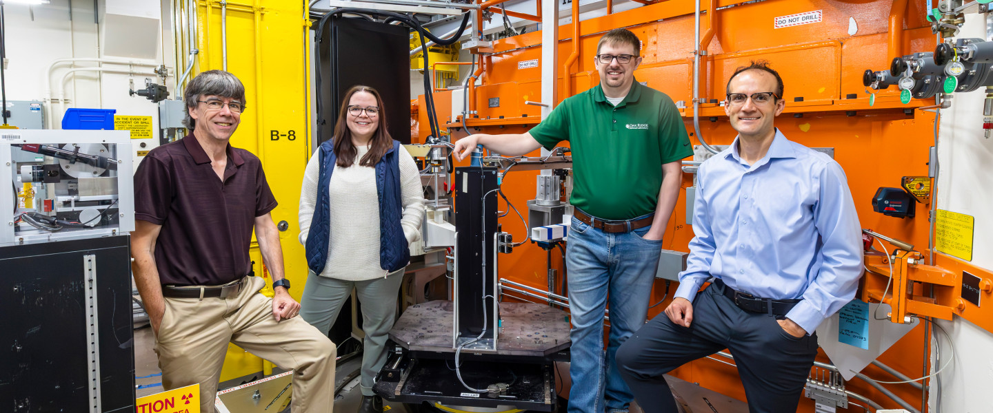
Please select link below to email the instrument team. Be sure to include your name and email address.
HIDRA User Guidance
This page provides guidance for new and returning users of the High Intensity Diffractometer for Residual Stress Analysis (HIDRA | HB-2B) at the High Flux Isotope Reactor (HFIR), Oak Ridge National Laboratory. For questions not answered here, contact the instrument team at [email protected].
Becoming a HIDRA User
Beam time at HIDRA is allocated through the peer-reviewed HFIR/SNS User Program. General users obtain beam time by submitting a proposal through the IPTS system. Proposals are reviewed twice per year. Rapid-access and proprietary beam time options are also available—contact the instrument team for details.
Before preparing a proposal, we encourage you to contact the HIDRA instrument team to discuss your scientific objectives, sample requirements, and whether HIDRA is the most appropriate instrument for your measurement. You can also review the instrument capabilities and specifications on the HIDRA overview page.
See the Neutron Sciences For Users section.
Prepare and Ship Your Samples
Sample Geometry
For Mapping Experiments
Residual stress mapping by neutron diffraction places specific geometric constraints on your sample that must be carefully considered before your experiment. The most important factor is path length
Path length is the distance the incident and diffracted neutron beams must travel through the material to reach—and then exit from—the measurement gauge volume. Because neutron attenuation is material- and wavelength-dependent, long path lengths reduce the count rate at the detector and can make near-surface or interior measurements impractical or statistically unreliable. In highly attenuating materials (e.g., titanium, nickel superalloys, or thick steel sections), path lengths of even a few centimeters can result in prohibitively long count times per point.
When planning the measurement grid for a mapping experiment, you should:
- Estimate the path length at every planned measurement point—not just the interior points, but especially edge points where the beam enters or exits obliquely through a corner or curved surface.
- Ensure the gauge volume is fully buried within the material at every point. A partially submerged gauge volume (pseudo-strain effect) introduces systematic errors in the measured d-spacing that can mimic residual strain.
- Consider sample orientation carefully: rotating the sample so that the scattering vector aligns with the direction of interest while minimizing path length through dense material can dramatically improve data quality.
- Account for the sample’s cross-section in all three orthogonal measurement directions—measurements along the transverse and normal directions of a plate or weld, for example, may have very different effective path lengths.
- For complex geometries (curved surfaces, tapered sections, or parts with internal features), use the HIDRA planning tools to simulate the gauge volume trajectory before the experiment.
To assist with pre-experiment planning, HIDRA provides access to tools on the NOVA NDIP platform. Under the Engineering Diffraction section of ndip.ornl.gov/nova, you will find utilities for path length calculation, attenuation estimation, and gauge volume visualization. These tools are designed to work with the HIDRA instrument geometry and are available to all registered users.
Download the
HIDRA Planning Tools Guide (PDF)
d₀ (Stress-Free Reference) Sample Preparation
Accurate residual stress calculation requires knowledge of the stress-free lattice spacing, d₀, for the material being measured. Without a well-characterized d₀, lattice strains cannot be converted into absolute stress values, and the measurement is only meaningful in a relative sense.
The best d₀ samples are small coupons cut from material that is chemically and microstructurally representative of the component being studied, but from which the residual stress has been fully relaxed. The recommended approach is:
- Cut d₀ coupons from a “sister sample” — a piece of the same heat, same processing route, and same nominal composition as the component, but not from the component itself.
- Use electrical discharge machining (EDM) to cut the coupons. EDM introduces minimal cutting-induced stress compared to saw cutting or milling, which can plastically deform the surface and introduce spurious strains.
- Target a coupon size of approximately 3x3x3 mm^3 to 5x5x5 mm^3. The coupon must be small enough that stress relaxation is complete in all three directions (a rule of thumb: each dimension should be no more than ~3x the grain size, and small relative to the stress gradient length scale).
- If a sister sample is not available, d₀ coupons may be cut directly from an unstressed region of the component (e.g., far from welds or deformation zones), provided that region is genuinely representative of the bulk unstressed lattice spacing.
- For materials with compositional gradients (e.g., dissimilar metal welds, graded alloys, or case-hardened steels), a spatially resolved d₀ map may be required. Discuss this with the instrument team before the experiment.
- Ship d₀ coupons together with the main sample and clearly label them. Plan sufficient beam time for d₀ measurements — typically 10-20% of the total experiment time.
Download the d₀ Reference Sample Preparation (PDF)
Shipping Your Samples
Shipping instructions for samples sent to ORNL are available on the HFIR/SNS For Users page. Please review all requirements carefully before shipping, as samples sent without prior coordination may be refused or delayed.
Before shipping, confirm your sample information in the IPTS system. Include a packing list that identifies each sample by IPTS number, sample ID, material, and mass. If your samples contain hazardous materials, radioactive material, or restricted substances, contact the instrument team and the ORNL sample receiving office well in advance.
Ship Back Your Samples After the Experiment
After your experiment is complete, instrument staff will assist with arranging return shipment of your samples. Provide an official institutional shipping address—residential addresses cannot be used for return shipment of samples measured at a nuclear research reactor facility.
Please be aware that samples that have been exposed to the neutron beam may become mildly activated depending on their composition. Most engineering alloys (steel, aluminum, titanium) clear quickly and can be returned without restriction. However, samples containing certain elements—particularly cobalt (Co)—may remain activated for an extended period and can only be received by appropriately certified facilities. Contact the instrument team before your experiment if your material composition is unusual or if you have concerns about activation.
Monitor Your Experiment and Data Collection Progress
Whether you are on-site or participating remotely, you can monitor the status of your HIDRA experiment in real time using the links below.
- HB2B DAQ Monitor — Live view of the data acquisition system: count rates, run status, detector health, and current motor positions.
- HIDRA Instrument Status — Current operational status of the instrument, scheduled maintenance, and beam availability.
During data collection, pyRS AutoReduction runs automatically on each completed sub-run, producing near-real-time 1D diffraction patterns and d-spacing values. Reduced data are accessible on the ORNL analysis cluster as soon as each measurement point is complete, allowing you to assess data quality and make adjustments mid-experiment.
Data Analysis and Visualization Using pyRS
HIDRA data are reduced and analyzed using pyRS (Python Residual Stress)
pyRS is an open-source Python package developed at ORNL specifically for HIDRA. It handles the complete workflow from raw 2D detector images through peak fitting to final stress and strain values, with uncertainty propagation at every step. A graphical user interface (GUI) is available for interactive analysis, and a Python scripting interface supports automated batch processing.
pyRS capabilities include:
- 2D detector image reduction: vanadium normalization, detector calibration, and azimuthal integration to produce 1D intensity vs. 2θ patterns
- Single-peak fitting (Gaussian, Lorentzian, Pseudo-Voigt) to extract peak position (d-spacing), integrated intensity, and peak width
- Strain and stress calculation using diffraction elastic constants
- Pole figure and texture analysis from azimuthal integration of 2D data
- Phase fraction mapping for multi-phase materials
- Automated AutoReduction during live data collection
- Visualization of strain maps, stress tensors, and peak fit quality metrics
pyRS is publicly available and can be installed via conda. Documentation and the source code are available at: github.com/neutrons/pyrs.
The primary software reference is: Fancher et al., J. Appl. Crystallogr. 54, 1886–1893 (2021). DOI: 10.1107/S1600576721010554
Download and Upload Your Data
All HIDRA raw data files (NeXus/HDF5 format, .nxs) and pyRS-reduced outputs are stored on the ORNL analysis cluster and are accessible to proposal team members immediately after each run completes. Data are organized by IPTS experiment number.
To transfer data between the ORNL cluster and your own computer, use an SFTP client such as FileZilla (Windows/Mac/Linux, free) or Cyberduck (Mac/Windows, free). Connect to:
- Server: analysis.sns.gov
- Protocol: SFTP
- Port: 22
You must have an active XCAMS account to access the cluster. XCAMS accounts are created automatically when your proposal is accepted. If you have trouble accessing your data, contact the HFIR/SNS User Office.
Finding and Downloading Data via ONCat
HIDRA data are also cataloged in real time in ONCat (oncat.ornl.gov)
ONCat is ORNL’s neutron and X-ray data catalog. It provides a web-based interface for browsing, searching, and downloading your HIDRA data files without needing to use the SFTP command line. All runs are indexed automatically by IPTS number, run number, date, and sample metadata as soon as data collection completes.
To access your HIDRA data in ONCat:
- Navigate to oncat.ornl.gov and log in with your XCAMS credentials.
- Select the HFIR facility and the HB2B instrument from the catalog browser.
- Filter by your IPTS experiment number to view all runs associated with your proposal.
- Browse individual run metadata — including sample name, count time, wavelength, slit settings, and motor positions — directly in the browser without downloading the full file.
- Download individual .nxs files or select multiple runs for batch download.
- Use the ONCat API for programmatic access if you need to automate data retrieval or integrate catalog queries into your analysis scripts. The API is documented at oncat.ornl.gov.
ONCat is particularly useful for verifying that all expected runs were recorded correctly before leaving the facility, and for accessing data remotely after your experiment is complete. The catalog is accessible from outside the ORNL network with your XCAMS login — no VPN is required to browse metadata or download data files. Visit: oncat.ornl.gov
Publish Your Results
When publishing results from measurements at HIDRA, users are required to:
- Include the standard HFIR facility acknowledgment statement in all publications. The required text is: “This research used resources at the High Flux Isotope Reactor, a DOE Office of Science User Facility operated by Oak Ridge National Laboratory.” If a specific proposal number was used, add: “The beam time was allocated to HIDRA on proposal number IPTS-XXXXX.”
- Notify the HFIR/SNS User Office of all publications, presentations, and other research outputs resulting from your beam time. This can be done through the IPTS system or by emailing the User Office.
- Review the full primary obligations regarding facility acknowledgment and publication reporting on the HFIR/SNS For Users page.
The primary instrument reference that should be cited in publications reporting HIDRA measurements is:
Bunn, J.R. et al. “The high intensity diffractometer for residual stress analysis (HIDRA), a third generation residual stress mapping neutron diffractometer at the high flux isotope reactor.” Review of Scientific Instruments 94, 035101 (2023). DOI: 10.1063/5.0122250